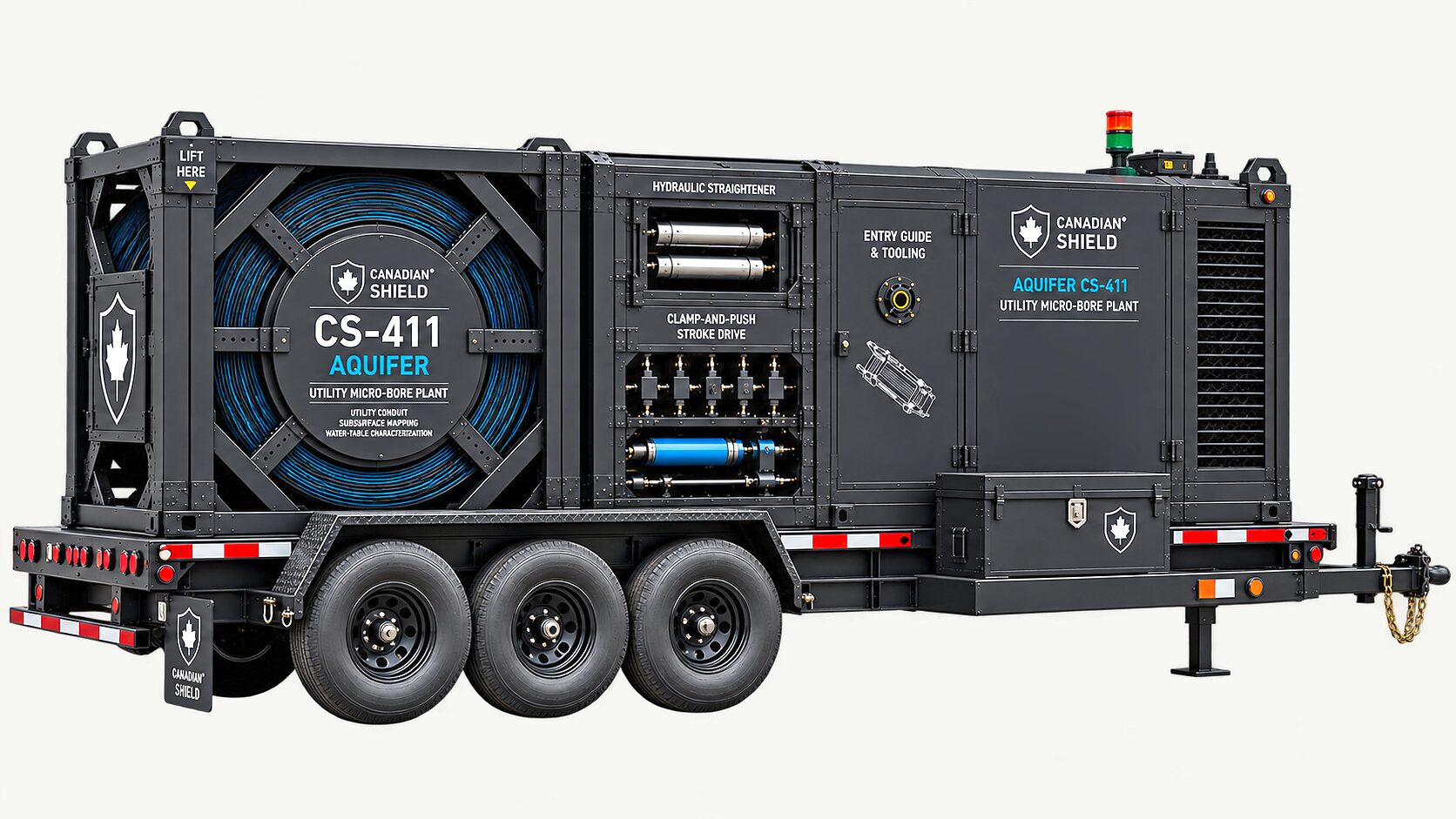
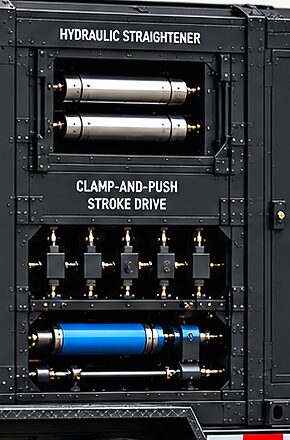
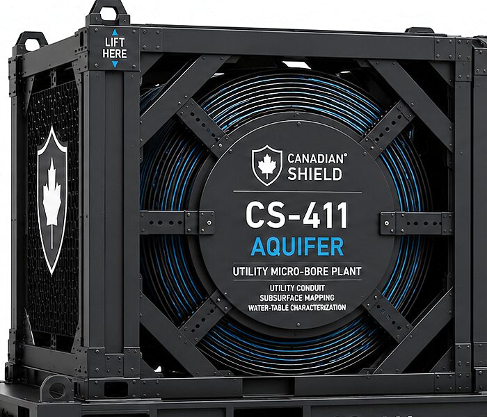
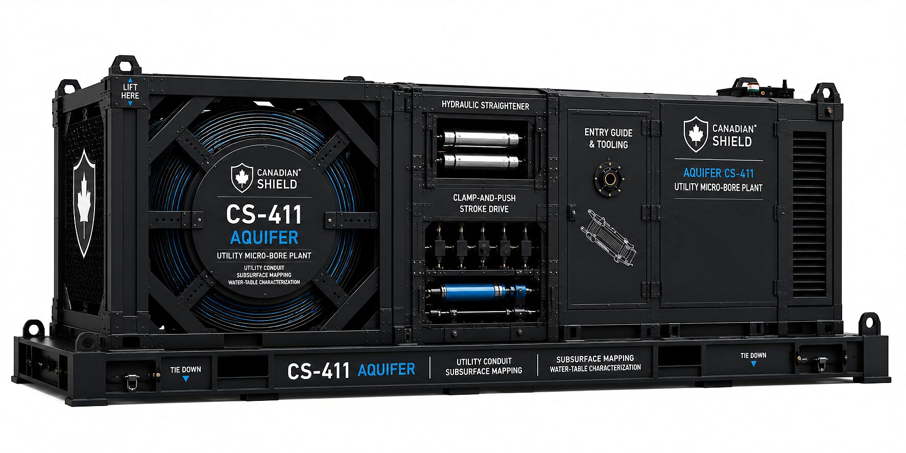
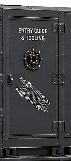
Aquifer CS-411 is CS-410 sent to utility ground: the same reel, the same hydraulic straightener, the same clamp-and-push stroke drive, the same entry guide. What changes is the head it carries, the fluid it pumps and the article it leaves in the ground.
Reel, straightener, stroke drive and entry guide are the same hardware on both programs. CS-411 differs by head kit, fluid package, completion goods and paperwork.
SHARED, UNCHANGED
Reel, straightener, drive, entry guide
The straightener carries across without modification and the stroke drive is the same patent-pending machine. A long bore asks it for endurance and an accurate stroke count rather than more force.
WHAT CHANGES
The head, the fluid, the article left behind
A rotary cutting head in place of a push-only nose. A fluid package that is the tool rather than a lubricant. Purchased completion goods, and a regime governing what may be pumped into ground somebody drinks from.
WHY IT PAYS
One rig, one tube, one drive, one console
Commonality here is mechanical. A part proved on one application is proved on the other, and a spare on the shelf serves both.
Working axial load in the tube stays in the single-digit kilonewton class for most of a long bore, far below what the drive delivers, so the long-bore duty changes what the machine is designed against rather than what it is. The entry guide bridges the same free span, with a surface conductor casing added for returns.
Everything above the ground line is the machine described on the CS-410 page. Everything below it diverges, and that is this page: a long horizontal bore, three services sharing one tube, a fluid package that does the cutting, an article left in the ground, and a water table to be found and respected. The family sits together on the Underground family page, and the buyer's view is who it is for.
The face
On the Defence Job the Fluid Lubricates. Here It Is the Tool.
Productive aquifers sit in saturated sand and gravel, the hardest ground a push-only head can meet. Face demand there runs an order of magnitude past what a coil tube delivers.
A 100 mm displacement head working saturated sands and gravels at cone-resistance classes of roughly 10 to 30 MPa asks for something like 79 to 236 kN at the face. The tube carries single-digit kilonewtons at the end of a long bore. The shortfall is a factor of 10 to 50, and no pump on the surface closes it, because the limit sits in the tube.
So the head cuts and the fluid clears. Jetting in saturated granular ground is mature practice at low weight on bit, so the mismatch belongs to the push-only head and not to the mission. That one decision is what makes CS-411 a different machine below the ground line while leaving it the same machine above it.
THE HEAD
Rotary cutting, not displacement
An HDD-class rotary bit of the Tricone or PDC family, turned by fluid power at the head. A coil tube cannot transmit controlled rotation, so nothing at surface turns or holds toolface.
THE FLUID
Three jobs at once
It relieves the face in saturated sand, holds the bore wall open, and carries cuttings out along the annulus. Sizing it sizes the prime mover, the fuel burn and the trailer.
THE RETURN
The annulus is the observation point
Returns come back to surface settlement, and what comes back is the only continuous read on the bore. A loss of returns while pushing is the precursor everything is watched for.
The tube bore
The Fluid Goes Down the Tube. The Completion Cannot Follow It.
The drilling fluid goes down the tube bore to the motor and the bit. A completion article does not fit down it in any size.
One tube goes into the hole and carries the fluid the head runs on: it turns the motor, drives the turbine-alternator at the head and carries the cuttings back along the annulus. The tube is CT-80 coiled tubing in every size, and its bore is 31.74, 50.77 or 76.20 mm across.
Down the tube bore
CS-411A
CS-411B
CS-411C
Coiled tubing, CT-80
38.10 × 3.18 mm
60.33 × 4.78 mm
88.90 × 6.35 mm
Tube bore
31.74 mm
50.77 mm
76.20 mm
Service completion
57 mm
DN90
DN140
Ream pass that opens the bore for it
Ø96 mm
Ø149 mm
Ø216 mm
The service completion is larger than the tube bore in every size, so it goes into the ground behind the string.
The finding that matters is in the completion row. A service completion of 57 mm, DN90 or DN140 is larger than the bore it would have to travel down, so nothing that completes a well travels down the tube; the completion goes into the ground behind the string, after a reaming pass has opened the bore for it. Payload through the tube is true for a sensor node and false for every completion article on the mission list.
Bore diameter
A Pilot Bore for Hole Cleaning. A Separate Pass for the Completion.
Pilot diameter sets the buckling cap, the flow, the pump and the volume that enters the formation. The completion is left to a separate reaming pass, with its own permit and its own fluid.
The obvious lever is the weak one. Clearance between tube and bore wall sets the load at which the tube buckles, and that cap scales as the inverse square root of clearance, so it moves slowly with hole size. The strong lever is flow: a bigger hole needs a great deal more flow to keep clean, and more pump to deliver it. So each pilot is sized to keep its own hole clean, not to fit the completion that follows it.
Pilot bore
Radial annulus
Ream pass, separately permitted
Service completion
CS-411A, Ø85 mm
23.45 mm
Ø96 mm
57 mm
CS-411B, Ø108 mm
23.84 mm
Ø149 mm
DN90
CS-411C, Ø149 mm
30.05 mm
Ø216 mm
DN140
The pilot is sized by hole cleaning alone. The completion goes into a bore opened by a separate reaming pass.
Separating the two keeps the pilot as small as hole cleaning allows. The ream is its own pass, with its own permit and its own fluid, so the fluid each pass puts into the ground is reported on its own, and that is the number a regulator asks for.
In-bore buckling
The Helix Is Not Extra Drag. It Is a Different Regime.
Push a coil tube along a horizontal hole and it does not stay straight. It goes sinusoidal, then helical, and the helix changes the drag regime rather than adding to it.
Four quantities set the onset: the tube's bending stiffness, its weight per metre, its buoyed lateral weight once fluid inside and around it is counted, and the radial clearance. What the onset does not show is the step that follows. Fully helical, the tube bears on the wall far harder than it does lying straight, and the contact force goes on growing as the square of the load. Published relations for helix formation spread widely, so it is carried as a band.
Size
Tube axial yield
Design push
CS-411A
192.6 kN
34.3 kN
CS-411B
460.5 kN
110.3 kN
CS-411C
909.0 kN
237.3 kN
CT-80 coiled tubing at a 552 MPa yield strength. The design push is half the helix yield cap.
A tube bent into a helix carries bending stress on top of its axial load, and the tube is not empty: on the smallest size, internal pressure alone adds enough effective force to buckle the string from the toe before any push is applied at surface. The helix cap is solved with that pressure-induced effective force in the bending term, and the design push is half of it in every size.
The clamp does not govern in any size, and its conforming dies are retained for tube life, not for capacity. The limit is the tube yielding inside its own helix, so the design push grows with the tube rather than with the drive.
The plant
Built in Three Sizes, Named by the Hole They Cut.
The pilot bore names the class, and everything follows it: the tube, the reel, the push the drive is designed against, and the article the finished hole takes.
The plant is a mobilization before it is a machine. The two smaller sizes travel as a single load. The largest carries its reel as a demountable module, over-height on the road at a 4.73 m outside diameter, and moves as a three-load spread.
Reaction is the check that decides the spread. The plant's own weight on a wet civil site is not a reaction anyone can count on, so the push goes into the ground through anchor points on the frame: two at 25 kN on CS-411A, six at 25 kN on CS-411B and six at 100 kN on CS-411C, whose demounted reel is not counted as sliding resistance. Screw anchors or a deadman are load-bearing, not optional.
CS-411A
CS-411B
CS-411C
Pilot bore
Ø85 mm
Ø108 mm
Ø149 mm
Ream pass, separately permitted
Ø96 mm
Ø149 mm
Ø216 mm
Service completion
57 mm
DN90
DN140
Design push
34.3 kN
110.3 kN
237.3 kN
Reel core radius
1.00 m
1.20 m
1.70 m
Reel flange outside diameter
2.50 m
3.18 m
4.73 m
Layers on the drum
5
5
6
Reel demountable
No
No
Yes
Design push is the helix yield cap divided by 2.0. The largest size moves as a three-load spread, its reel a demountable module.
The tube
Every Pass Is Plastic. The Reel Only Softens It.
Yield strain for coiled-tubing steel is about 0.3 per cent. The tube bends onto the drum at 1.9 to 2.6 per cent and unbends off it again, so its life is counted in trips.
Bend strain across the drum is the tube's outside diameter over twice the core radius, stated here as the full range rather than as the amplitude, so the only lever the reel offers is a bigger core, and a bigger core is mass and transport height. Across the three classes the tube grows faster than the drum does, and the fatigue margin narrows as it goes.
CS-411A
CS-411B
CS-411C
Inner-fibre bend strain across the drum
1.91%
2.51%
2.61%
Trips available
27.6
16.7
15.5
Trips required
15.0
15.0
15.0
Margin
1.84×
1.11×
1.03×
A trip is one deployment and recovery of the string.
The largest class clears its requirement by 3 per cent, which is not a margin that survives a lost count. So the fatigue ledger is load-bearing rather than a record-keeping convenience: the count belongs to the tube, follows it between jobs, and is taken from the reel encoder and the injector cycle counter. The straightener adds to the account too, since driving the tube through it forms a travelling plastic hinge at the centre roller.
That accounting also makes a completion left in the ground attractive on the arithmetic and not only the schedule: it spends about one deployment of tube life. Every re-entry to develop a lateral or service a sensor string spends another.
Bore stability
The Fluid Holds the Hole. So the Pump Does Not Stop.
A static column of fluid gives only a thin overbalance against saturated sand. Circulating adds support, unevenly, and the hole is never left without it.
Mixed density is held to SG 1.05 by mud balance on site, so a static column stands only a little above the formation's pore pressure. Circulating adds annular friction, and annular friction accumulates from the toe back to the exit, so the support it buys is not evenly spread: the bore is best supported at the toe while circulating and most thinly at the heel, the part that has been open longest.
Pressure is not the whole story: what holds a horizontal bore open in sand is filter cake, soil arching and the fluid's gel strength working with the overbalance rather than instead of it.
Two operating decisions follow, and they are one decision. Circulation is never stopped with the string in an open lateral. And because a stroke drive that pauses to reset is a drive that stops advancing, the injector advances continuously on two clamps, one holding the load while the other resets.
What goes into the ground
A Regulator Asks for a Volume. Penetration Rate Decides It.
Hole cleaning fixes the flow. Flow, times the length of hole, divided by the rate of penetration, is the volume that leaves the bore and enters the formation.
The pilot is sized by hole cleaning alone and the completion is cut later by a separate pass, so the flow belongs to the pilot and the volume that follows it is reported pass by pass. What goes into the ground is written as an exclusion rule, not a recipe: water, sodium bentonite and a soda-ash pH buffer, and nothing else in aquifer contact unless it carries a third-party drinking-water listing. Delivery and return flowmeters measure the loss to the formation on every bore.
PENETRATION RATE
An environmental control first
Volume lost scales as one over the rate of penetration, because flow is fixed by hole cleaning. Doubling the rate halves the volume that goes into the ground, so penetration rate is written into the operating procedure as an environmental control.
THE FLUID ITSELF
A short list, and it is not ours
Work in a potable aquifer restricts the fluid to listed products, which in practice means plain bentonite and a short list of listed polymers. The provincial regime decides the rest, before the engineering does.
THE SQUEEZE
One constraint pulling two ways
A weaker fluid suspends cuttings less well, which asks for higher annular velocity, which asks for more flow, which puts more volume into the aquifer. The rheology limit and the environmental limit are one constraint seen from opposite ends.
Guidance
No Radio. No GPS. Gravity, Rotation and a Person at the Console.
There is no radio and no GPS aboard, in any size. The bore is flown on sensing at the head, and a person at the console steers every bore.
Inclination comes from accelerometers and is referenced to gravity, so it does not drift; its error is a systematic bias rather than something that grows with time in the hole. Azimuth is taken by a continuous gyro. A gyro needs no non-magnetic spacing, and it gives a valid toolface below 5° of inclination, where gravity toolface is undefined.
Its limit is physics. North-seeking works on the horizontal component of the earth's rotation, so azimuth uncertainty scales as one over the cosine of latitude, and a near-horizontal hole is close to the worst attitude for it. The answer is stationary re-references, at an interval short enough that the unsurveyed bow stays small: at 30 m the bow is 0.196 m, 0.65 per cent of the reference cover.
VERTICAL
±2.0 m in a 4.0 m stratum
Centred in a 4 m water-bearing layer the budget is ±2.0 m. Steering resolution, sensor-to-face extrapolation, station interpolation and the entry tie-in take 0.84 m of it, leaving 1.82 m for the sensor and an inclination accuracy better than 0.12°.
LATERAL
Cross-track matters less, until it does
A lateral stays inside a stratum metres thick and hundreds wide, so the budget goes on inclination and tie-in. The exception is a lateral steered to a legal boundary, where azimuth becomes a compliance measurement.
THE TARGET
Geology dominates the instrument
A sand mapped from boreholes tens of metres apart carries its own depth uncertainty, and half a degree of dip walks the target several times the vertical budget. Grade holding is a geological problem before an instrument one.
Doctrine
No radio. No GPS. A person at the console.
There is no radio and no GPS aboard, in any size. The plant stays on the surface and nothing enters the ground but the tube and the head, so nobody goes into the hole. Carriers and conduit tools, never munitions: no warhead, no fuze, no energetic material. Every design in the family is patent pending.
Nothing at surface turns the bit. A positive-displacement mud motor with a bent housing turns it in all three sizes, and toolface is set by an electrically driven orienting sub that closes its loop on a downhole toolface measurement, because the string would absorb any reference taken at surface. Power for the tools is generated at the head, by a turbine-alternator in the mud stream.
A person at the console steers every bore. On loss of the data path to the head, advance stops and the string is pulled back: a bore advanced blind past its allowance has an unknown cover.
Recovery
Give Up the Head. Keep the Tube.
The consequence is not a lost asset. It is a permanent steel and electronics installation inside somebody's potable aquifer, so the platform gives up the head and keeps the tube.
The string cannot be rotated, backed off or jarred, so recovery rests on two things only: overpull, then a deliberate release. A bore that collapses onto the tube holds it along the whole collapsed length, and a few seconds of running sand after a pump trip is enough to do it, the same reason circulation never stops.
So a release sub is in the string on every bore, in every size. When it fires, the tools stay at the toe and the tube comes back; without it, a string that cannot be pulled free is abandoned in the hole whole. The design rule follows from that: if the head can be left in an aquifer, the head is built to be left in one.
No lead, no cadmium, no brominated flame retardants, no seals containing PFAS
Housings, seals and potting from materials listed for drinking-water contact, or inert
Every article left in place logged to the well record
What the bore leaves
The Pilot Bore, Then the Article. Sometimes the Article Is the Record.
A screen pulled back into a mud-filled lateral is a pressure boundary, sized on the case that lasts decades rather than the one that lasts an hour.
Pulled in empty through a mud-filled bore, the screen sees the full mud column for about an hour. In service, pumped down to near the intake, it sees the full formation head for decades. The installation load is slightly larger and it happens first, so a fast reading concludes that installation governs. A fifty-year modulus retention belongs to the service case, and once each case carries its own modulus the service case governs.
Open area is not the constraint on a small screen. What the small diameter costs is conveyance inside the pipe, and over the length of a lateral the pipe limits the yield long before the screen does.
Not every bore ends in a well. Where the mission is characterization the record is the product: the head logs conductivity, moisture and strata identification as the bore advances, and piezometers and sensor strings are emplaced along the line. The buried sensing node is a program of its own, on CS-430.
Fit
Where This Plant Earns Its Place, and Where It Does Not.
The geometry decides most of it, and the difference is worth stating before a site visit.
WHO IT IS FOR
Owners of ground that has to stay open
Civil and mining contractors putting dewatering drains under an excavation, a slope or a working face, where gravity does the work and nothing needs a pump
Utility, pipeline and telecommunications owners installing conduit along a planned alignment without opening a trench
Programs that need the ground characterized along a line rather than at a point, with water table, moisture and strata logged as the bore advances
Managed aquifer recharge, the same lateral run in reverse duty, which needs no pump either
Trenchless and directional-drilling contractors who already sell this work
WHAT IT IS NOT
The jobs this plant does not take
Not a pumped production well on its own geometry. A submersible pump does not fit an Ø85 mm surface-launched lateral; that mission takes a vertical caisson with laterals kicked off below the water table
Not a machine that goes into the ground. The plant stays on the surface and nothing enters the hole but the tube and the head
Not radio-linked and not satellite-guided, in any configuration
Not a munition or a component of one: no warhead, no fuze, no energetic material, in any variant
Not a rig that reacts its push on its own weight. The anchors carry the load and are part of the spread
How it starts
Bring the Alignment. We Bring the Mechanism.
Enquiries are screened and nothing here is an offer. The way in is a working session with engineering.
Send the alignment you have in mind, the ground it runs through and the article you need left in it. What follows is a conversation about the pilot bore the ground will take, the class that suits it, the fluid the regime allows and the reaction the site can offer. Export posture is counsel-first, with permits per shipment.
All Underground family designs are patent pending; international transfer is export-controlled and subject to Canadian government permits taken per shipment, and nothing on this page is an offer.